I want to describe here some schematics for a power switch. The soft power switch is in fact a electronic switch ( no relay, no moving parts) that can be used as a ON/OFF for a certain device.
The classical way to switch ON/OFF a device is to use a flip switch like this :


But this mechanical switch is expensive and can break after a wile.
The other big disadvantage is that it require the mains AC line (supply line) to physically pass through that switch. So if for example you want to put the ON/OFF switch on the front panel of a device you have to go there with AC 110/220V mains. This can create problems (noise, interference…)
Beside this some people want a “fancy” ON/OFF function with only a simple push button. Like this:


So The switch is very small and can be integrated directly on the PCB board. Beside this there is very small voltages/current passing so there is no risk of electroshock.
Usually this type of application use DC voltages in the 3-24V domain. They are used often to start a board that has micro-controller or a small electronic device.
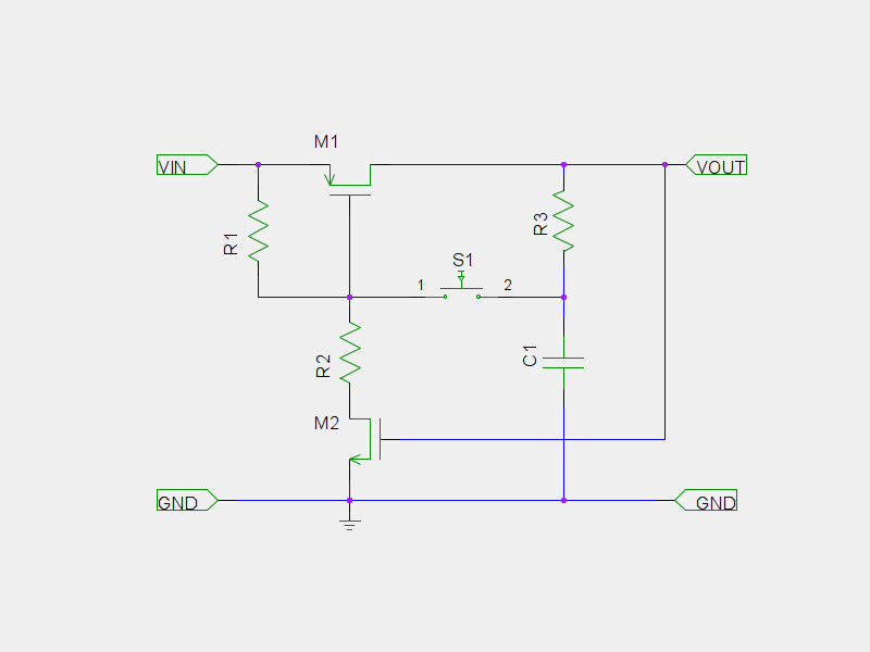
The following possibilities are shown below:
1: 
2:

3:

4:

5:

6:

7:

8:

9:

10:

11:

12:

13:

14: